Well , here and there these questions are popping on Diyaudio.com – how to check/adjust bias (Iq) ,offset(s) and gain on my X(A)xxx.? PL amplifier; this tutorial will address that.
Take in account that older PL amps are having (small) mosfet based output stage biasing generator , while later ones are having TL431 generator iteration – with some specimens finished without NTC compensation – exactly as amp shown in pictures.
However, I’m sure that you’ll find same logic (shown here) applicable also to earlier models.If not ,and you need some info regarding earlier models, contact me either through blog e-mail thingie , or on diyaudio.com.
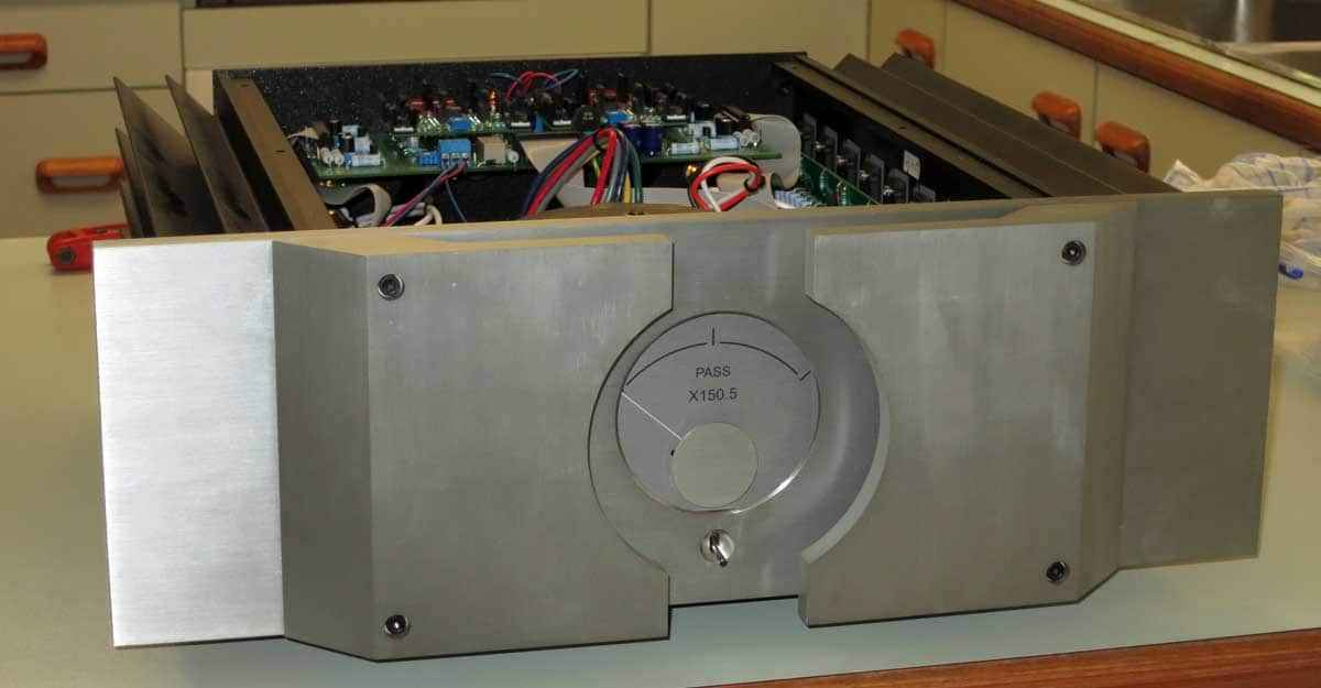
Amplifier shown here is X150.5 , late issue (circa 2007 , according to pcb text) , being in possession of DiyA fella known under witty Old’n’Cranky moniker.
Few general pictures for start;all pictures in post will open either in gallery or new tab,in full resolution.
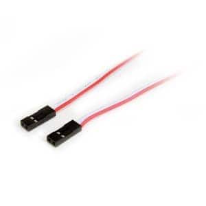
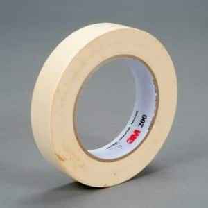
What you’ll need (besides adequate screwdrivers) is : two voltmeters , paper masking tape (1-2 inch wide) and two pin header cables ( at least 1 foot long).
Now , we can start,with Iq setting.
Unscrew top cover from amp – put masking tape all around cover edge/perimeter – to prevent scratching of case and cover itself , during repetitive opening/closing of case.You can make also two “ears” with tape on two opposite sides, to have sort of pull-up handles.
Ground all inputs ; that’s easiest putting U shorts in XLR thingies and shorts in RCA input thingies ; those you can make from cheap plastic RCA jacks , solder shorts between hot and GND.
Let first work on Iq setting , say left side ( looking from front of amp).
Connect two pin header cables to headers on pcb , marked as A bias and B bias,which I also marked in red rectangles:
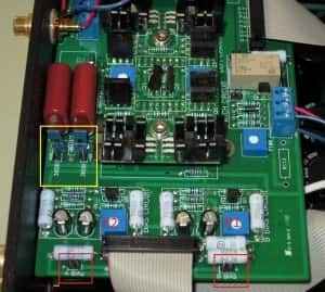 Polarization of header cables is irrelevant – just ignore possible negative reading on voltmeters later.
Route header cables out of amp ,put lid on , connect voltmeters on header cables , set to 200mVdc range; be careful with probes/cable ends – you don’t need unfortunate contact between them or any of them to amp case – result of that mishap isn’t catastrophic for amp itself , but you’ll burn either tiny traces or wires in ribbon cable , implemented in that monitoring circuit.You still don’t need those voltmeters powered on – you can leave them in Off state.
Now – with no load on amp outputs , with lid on , with voltmeters connected to cables (secured from shorts) …. triple check ……. power da amp , and go somewhere to spend at least one hour of (other type of) quality time 😉 .
=================================================
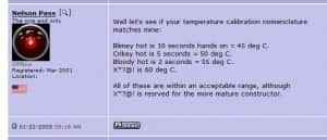
OK – you’re back , amp is (hopefully) in temperature equilibrium and now’s the time to remind you of Papa’s Palm Rule :
You can either practice his palm approach , or you can fiddle with your laser temp measuring thingie , or whatever you have.
Power up voltmeters , read what they tells you , write down on paper , same as temperature of left heatsink… just to have proper reference , where you started.
For X150.5 , approximate goal of reading across A bias and B bias points is between 110mV and 140mV ;both readings must be the same.
Why I’m saying approximate ……….. because Papa wrote this numerous times:
All Pass Labs amplifiers are designed to operate at about 30 deg C. above the ambient temperature, as measured on the top of the heat sinks. One of the reasons that this temperature is chosen is that the sensitivity of human skin to heat is non-linear in this region, and you can fairly reliably tell if the temperature on the heat sink is 50 to 55 deg C. by touch. If you can put your hands on the top of the heat sink for about 5 seconds, then you are close to the correct operating temperature.
The temperature test is the final judge of correct bias on these amplifiers. Reading bias voltages on the MB board is a good indicator, but if the temperature is too high or low, then adjustment is necessary.
Now you know the drill – by heatsink temperature you decide does amp needs upping, lowering or just tweaking of A bias and B bias.
Necessary change is best made with always same and simple procedure -remove the lid , tweak adequate trimpot (see that picture above – A header/adjacent P2 trimpot , B header/adjacent P1 trimpot) , put lid back,wait at least 20 min. for temperature equilibrium.
NB-approach trimpot fiddling with extreme care , small steps , each time no more than 10% change of prior value on voltmeters.
Papa , again :
Clockwise rotation of P1 and P2 on MB2 will raise the bias of the corresponding output stage. Do this very carefully, as it is possible to damage the amplifier accidentally during this adjustment. Always monitor the amplifier current draw and the bias voltage on the sensing pins during adjustment. If you don’t see a change in the pin voltage, check to be sure that you are reading the proper set of pins – the ones associated with that particular potentiometer.
There will be a slight bias drift as the amplifier heats up. For this reason, we recommend initial bias at 2/3 of the desired final value and then readjustment in half-way steps to the goal value as the amplifier warms up. An amplifier which has operated for an hour at a particular value is assumed to be stable at that value….
Repeat above procedure as much times as needed to arrive on your desired goal/wanted heatsink temperature.
When done , open the lid , and carefully remove header cables from left side of amp , and re-connect them to right side :
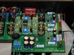 Again – A bias and B bias headers (red rectangle) , P2 for A Bias , P1 for B bias.
Repeat procedure explained /done for left side in same manner – as much times as needed to end in same heatsink temperature ballpark .Be patient and do not forget how important is to put lid back after each step.
When you done with that (both channels) , you can open the lid and carefully remove header cables from pcb, put lid back, leave amp On.
Time for output offsets.
X(A) amps , being bridged amps in topology , are having both outputs per channel floating , in reference to ground/amp case.
So – we are going to check/set two offsets for each channel :
–Differential offset – possible DC voltage between positive and negative output post,
–Absolute offset – possible DC voltage between any of output posts and Ground.
SO – let’s go – choose one channel , connect one voltmeter between + and – output posts,connect second voltmeter between any of them (say + post) and either GND or amp’s case .If RCA jack gnd is exposed , you can put clip there.
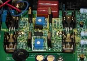
Now – pictures are pretty self-explanatory :
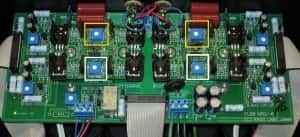
As written on UGS pcbs , P1 DIFF is (logically) for Differential offset , P2 ABS is for Absolute offset.
I marked them in gold rectangle – P1, white rectangle -P2.
Same approach as for Iq – open the lid,tweak trimpot,close the lid , wait until you can see that reading on voltmeters is steady.
Repeat above procedure , as long is needed to have these values ( again quoting Papa) :
On UGS5 P1 is used to adjust the differential output DC of the amplifier. P2 is used to adjust the absolute DC offset at the output of the amplifier.
P1 is adjusted with a DC voltmeter connected across the + and – output terminals, and is adjusted to 0V with a tolerance of about 10 mV or so.
P2 is adjusted with a DC voltmeter connected from ground to either output, and is adjusted to 0V with a tolerance of 100 mV or so. This DC is not seen by the load, but a low value is desirable, as high offset cuts into the maximum output swing of the amplifier.
Both P1 and P2 on UGS5 should be re-adjusted at operating temperature after warmup.
When you’re done with first channel , move both voltmeters accordingly to second channel, repeat entire procedure.
OK , now to gain settings :
As Papa (again ) sez :
The gain of the amplifier is adjustable from 26.6db to 30db by the jumpers found on the board near the inputs. Jumpered, they are 30dB. Unjumpered, they are 26.6db
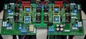
and from this picture (two and two jumpers , pair per channel , one per phase ) , jumpers in red circles :
…..everything is pretty much clear …….
Power amp off , remove masking tape from lid , put it back , screws too ….. put amp back in system and enjoy in better sleep ………..
🙂

